
Trilobite
1.4
User Guide

©
Darwin Arts L.L.C., 2016
|
|
|
|
|
|
Trilobite
1.4 |
|
|||
|
|
|
||||
Trilobite provides a palette of audio signal modules which may be connected together using the Patch Visual Editor. This section enumerates and describes each module type in its own page containing the information and tables shown as a template on this page.
Topics on this page include:
Module Description
Static
Parameters
Input Ports
Output
Ports
Module Type List
Each Module type is described in varying detail, with an overview of how signals are generated, manipulated, or consumed. Where appropriate, further technical or historical links are provided.
Static parameters are the Module attributes which may be manipulated in the module's Popup Parameter Dialog. These values may only be changed manually in the Patch Visual Editor, or auto-generated when Patches are evolved using the Population Editor. They will remain fixed during general usage.
Static parameters for each Module type are tabulated as follows:
|
# |
Title |
Type |
Description |
|
The static parameter index, starting with 0. |
The label for this static parameter. |
The parameter variable type. Possible types are:
|
A brief description of the purpose of this static parameter. Where applicable, the range of possible values is expressed as: Range[from, to] and the slider behavior is expressed as linear or logarithmic. |
These are the ports lining the right side of each module, and are the conduit by which the module receives signals from other modules (see the Patch Canvas page for more info). For most module types, each port signal has a unique purpose, but some Module types allow additional Input Ports of duplicate purpose to be added manually using the Module Popup Menu. Every module Input Port has an input signal scalar value and an optional mapped parameter as described in the Patch Basics page. Individual module types may or may not apply this these scalars to each input signal.
Input Ports for each module type are tabulated as follows:
|
# |
Title |
Description |
Input Scalar Used |
|
The Input Port index, starting from the top with index 0. For module types supporting manual addition of input nodes, this will be expressed as: offset + N, etc. |
The title of this port, as seen when holding the mouse over a port as described when making port connections. |
A brief description of how this input signal is used by the module. |
Will contain “YES” or “NO”, depending on whether this Module type applies the scalar values internally |
The number of module Output Ports is always fixed, although each of these may or may not generate signal based on internal module state.
Output Ports for each module type are tabulated as follows:
|
# |
Title |
Description |
|
The Output Port index, starting from the top with index 0. |
The title of this port, as seen when hovering the mouse cursor over a port when making port connections. |
A brief description of this output signal. |
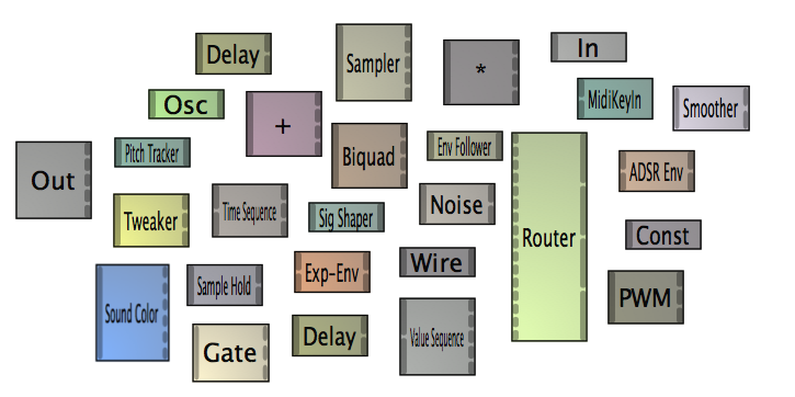
Modules types include:
Output
Input
Oscillator
Constant
Sum
Product
Biquad
Filter
Midi
Input
Delay
Signal
Shaper
Envelope
Follower
Exponential
Pulse
Pitch
Tracker
Sampler
ADSR
Envelope
Wire
Noise
Source
Tweaker (pro
version only)
Sample
Hold (pro
version only)
Value
Sequence (pro
version only)
Time
Sequence (pro
version only)
Pulse
Width Modulator (pro
version only)
Router
(pro
version only)
Sound
Color (pro
version only)
Gate
(pro
version only)
Smoother
|
|
|
|