
Trilobite
1.0
User Guide

©
Darwin Arts L.L.C., 2015
|
|
|
|
|
|
Trilobite
1.0 |
|
|||
|
|
|
||||
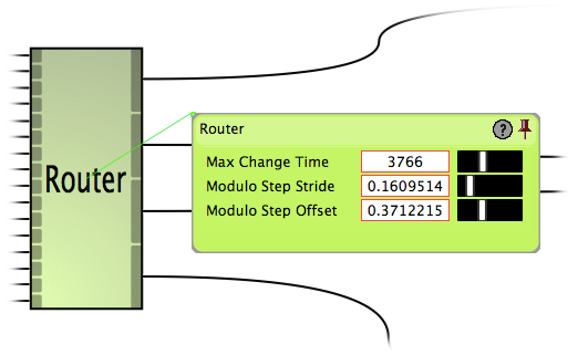
The Router Module re-routes a single input signal to any one of 16 output ports based on a matrix routing address scheme to its other input ports and based on its static parameter values. The routed signal will crossfade smootly between two output ports when the route changes.
For a key to understanding the tables on this page, see the Module Types page.
|
|
The Router Module is available in Pro Version only. |
Adding input ports is not enabled for this module.
|
# |
Title |
Type |
Description |
|
0 |
Max Time Change |
Fixed |
Sets the time in milliseconds for a crossfade from current output port to the next port specified by X-Y routing parameters. During the transition time, routing parameter input will be ignored. |
|
1 |
Modulo Step Stride |
Floating-point |
If you think of the Router output ports as being a 4x4 matrix, this value expresses what delta change in the input Route Address Y signal (Port 1) will move the routed output from one row to an adjacent row. Mappings will wrap around the range [0.0, 1.0]. |
|
2 |
Modulo Step Offset |
Floating-point |
If you think of the Router output ports as being a 4x4 matrix, this value expresses what delta change in the input Route Address X signal (Port 2) will move the routed output from one column to an adjacent column. Mappings will wrap around the range [0.0, 1.0]. |
|
# |
Title |
Description |
Input Scalar Used |
Parameter Scalar Used |
|
0 |
Input Signal |
This signal will be routed to an output port, or transition between output ports, based on the X-Y address values received by Ports 1 & 2. |
NO |
NO |
|
1 |
Route Address X |
If you think of the output ports as a 4x4 matrix, this value dictates the column of the output port address, with the modulo addressing values dictated by static parameter Modulo Step Stride. |
YES |
YES |
|
2 |
Route Address Y |
If you think of the output ports as a 4x4 matrix, this value dictates the row of the output port address, with the modulo addressing values dictated by static parameter Modulo Step Offset. |
YES |
YES |
|
3 |
Interval Scalar |
This signal will act as a scalar of the Max Change Time static parameter for transition between output ports. It is internally constrained to the range [0.001, 1.0] |
NO |
YES |
|
# |
Title |
Description |
||||||||||||||||
|
N |
Routed Output #X - Y |
16 outputs which input signal may be routed to. Values for vary between [0, 3]. The X-Y position indicates the matrix position of output, in the following pattern:
|
|
|
|
|
